
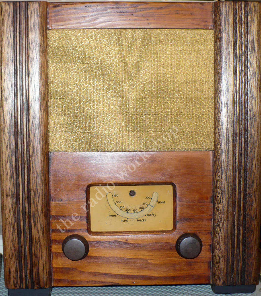
The Radio appeared in 1944 when shortages of new domestic radios and replacement parts had become serious. More than 40 British radio manufacturers participated in the scheme under the Wartime Joint Enterprise, producing essentially the same government-standard design. The sets were deliberately sold without the manufacturer's normal brand name; a code stamped on the chassis identified the actual maker for servicing purposes. More than a quarter of a million were produced.
The simplicity was intentional. There was no elaborate tuning scale, tone control or decorative trim. The original mains receiver covered Medium Wave only, reducing the number of coils, switches and other components required.
The Utility Radio was designed around wartime economy rather than appearance. Its straightforward wooden cabinet, small tuning scale and two controls saved timber, metal, components and manufacturing labour. Standardisation also meant replacement components could be supplied without having to maintain completely different spares for dozens of radio makes.
The basic design is generally credited to Dr G. D. Reynolds of Murphy Radio, although production was distributed among many British manufacturers. Murphy-built examples carried the manufacturer's code U7.
SERVICE MANUAL PREVIEW
The Trader service sheet for the Wartime Civilian Receiver, AC model, is available to members, along with the battery model and the production modifications list. Here's a taste of what's inside.
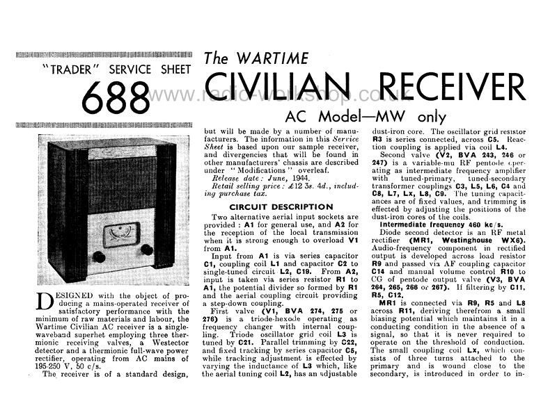
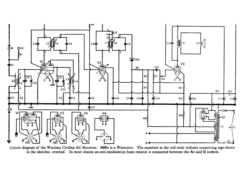
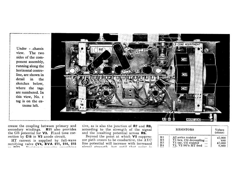
These pictures are faded on purpose, just for this preview. Members get the complete service sheet, unfaded, to view and download.
The service sheet includes:
- The full circuit diagram, with the coil connection numbers
- Capacitor and resistor values
- Valve analysis, with the voltages and currents
- Step by step circuit alignment
- How to remove the chassis
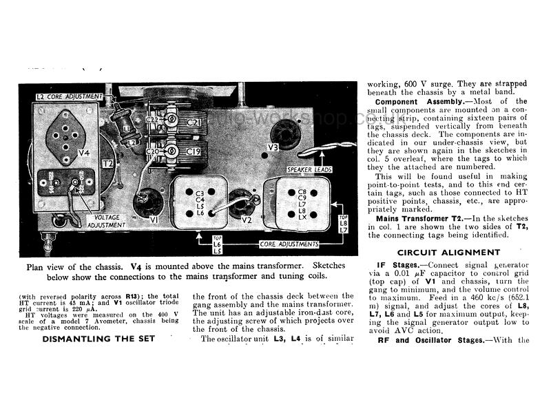
- Photos of the top and underneath of the chassis, with sketches of the coil and transformer connections
- The list of manufacturers and their code numbers, with the changes each one made
- A table of replacement valves for the BVA numbered types