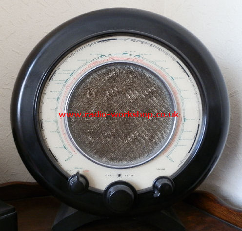
The Ekco A22 is one of the best-known British valve radios, particularly distinctive because of its round cabinet. It was made by E.K. Cole Ltd. (Ekco), Southend-on-Sea, and was introduced in November 1945, immediately after the Second World War. It was the last of Ekco’s famous series of round radios, a design tradition that began with the AD65 in 1934. The round Ekco designs are associated with architect and industrial designer Wells Coates.
The three controls across the bottom are, from left to right, waveband selector, tuning, and on/off plus volume. One particularly attractive feature is the circular tuning scale. A moving illuminated cursor travels around the dial as the radio is tuned.
Cabinet and versions
The normal A22 was produced in brown/walnut-coloured Bakelite, with a bronze-coloured loudspeaker surround. A black Bakelite version was also produced, normally with a chrome speaker surround. There was also a well-known green example associated with the 1946 “Britain Can Make It” exhibition at the Victoria and Albert Museum; surviving coloured examples need careful authentication because later reproductions and recoloured cabinets exist.
Valve line-up.
ECH35 mixer/oscillator. EF39 IF amplifier. EBL31 detector. EBL31 audio output.
SERVICE MANUAL PREVIEW
The original Ekco service data for the A22 is available to members. Here's a taste of what's inside.
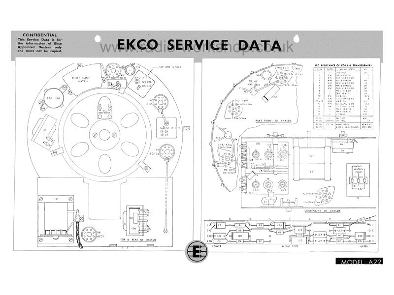
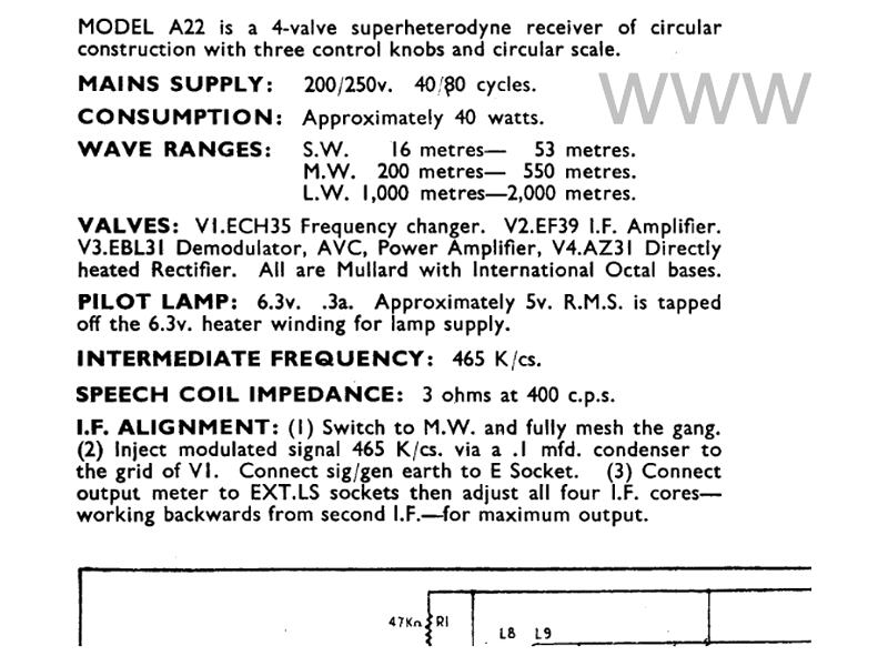
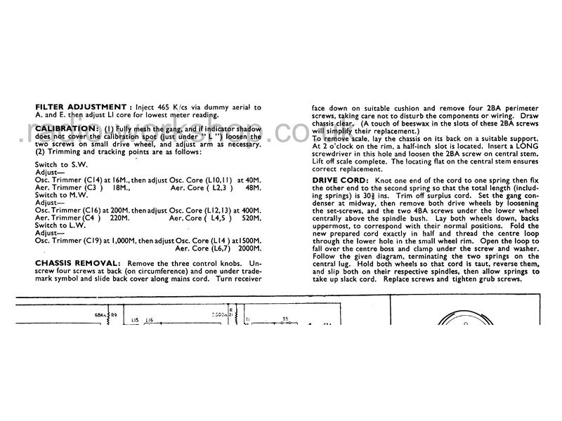
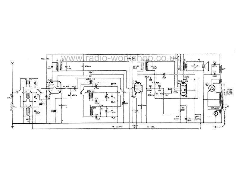
These pictures are faded on purpose, just for this preview. Members get the complete service data sheet, unfaded, to view and download.
The service data sheet includes:
- Drawings of the front, back and underside of the chassis, with every component labelled
- DC resistances of the coils and transformers
- The specification and valve line-up
- Step by step IF alignment, with trimming and tracking points for each waveband
- How to remove the chassis
- How to fit a new drive cord and replace the scale
- The full circuit diagram