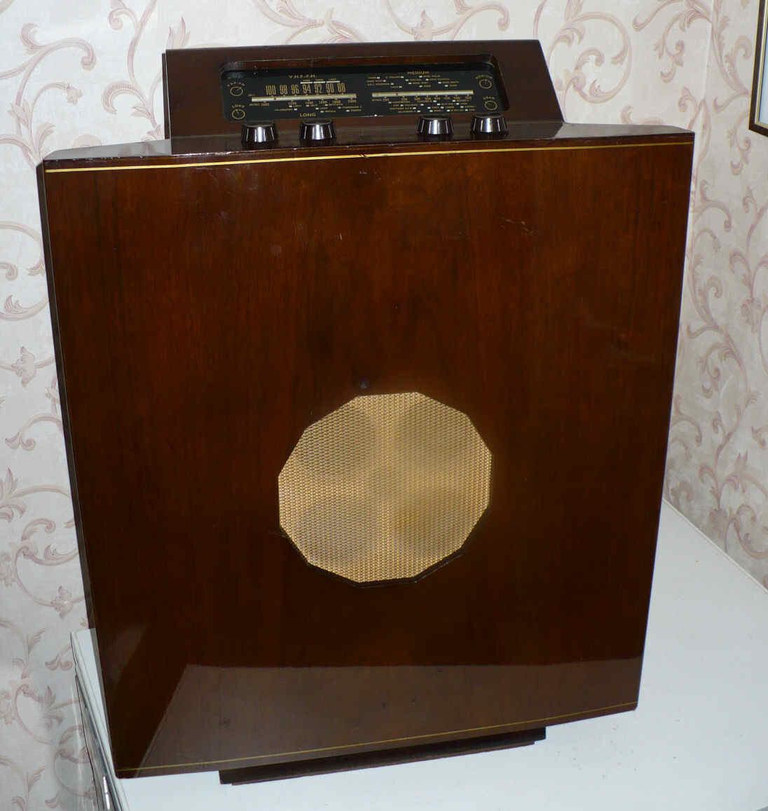
The Murphy A272C is a distinctive British valve radio introduced in August 1956 by Murphy Radio Ltd of Welwyn Garden City, Hertfordshire. Unlike most table radios of the 1950s, the A272C was designed as a large, floor-standing baffle console radio, with an unusually wide wooden front panel and a substantial loudspeaker. It was designed to deliver particularly good sound quality.
Murphy Radio was known for producing technically interesting radios with unconventional cabinet designs. The A272C is a good example of this approach. It appeared shortly after the introduction of FM broadcasting in Britain in 1955, offering listeners both traditional AM broadcasts and the newer VHF/FM service.
The large wooden front isn’t simply decorative. It acts as an acoustic baffle, helping the 10-inch loudspeaker reproduce bass frequencies more effectively. This was Murphy’s way of obtaining a fuller sound without the complexity of a separate speaker enclosure.
The valve line-up comprises ECC85 (or Mazda 6L12), 6C9, 6F18, EABC80, 6P1 and UU9.
SERVICE MANUAL PREVIEW
The original Murphy service manual for the A272 and A272C is available to members. Here's a taste of what's inside.
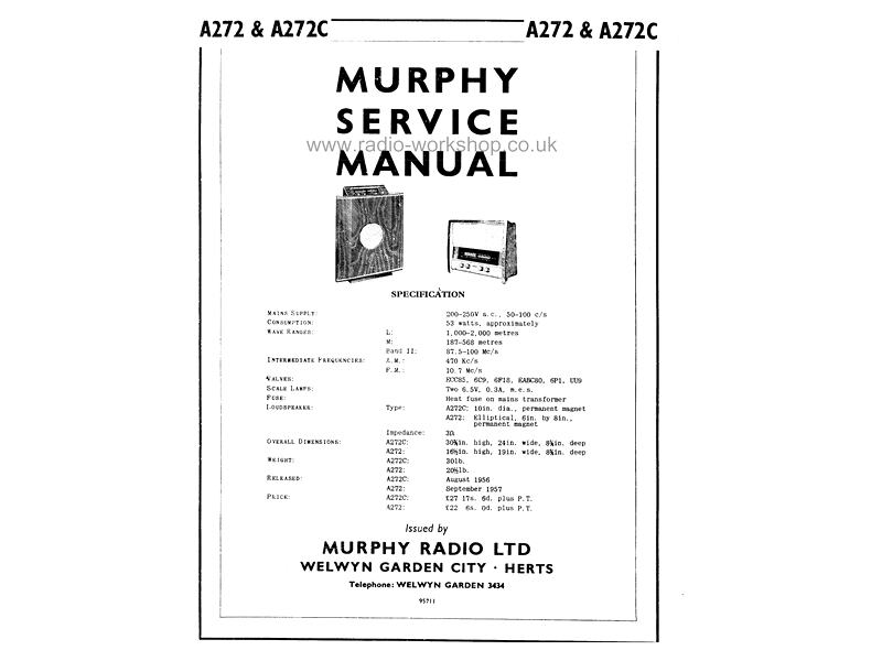
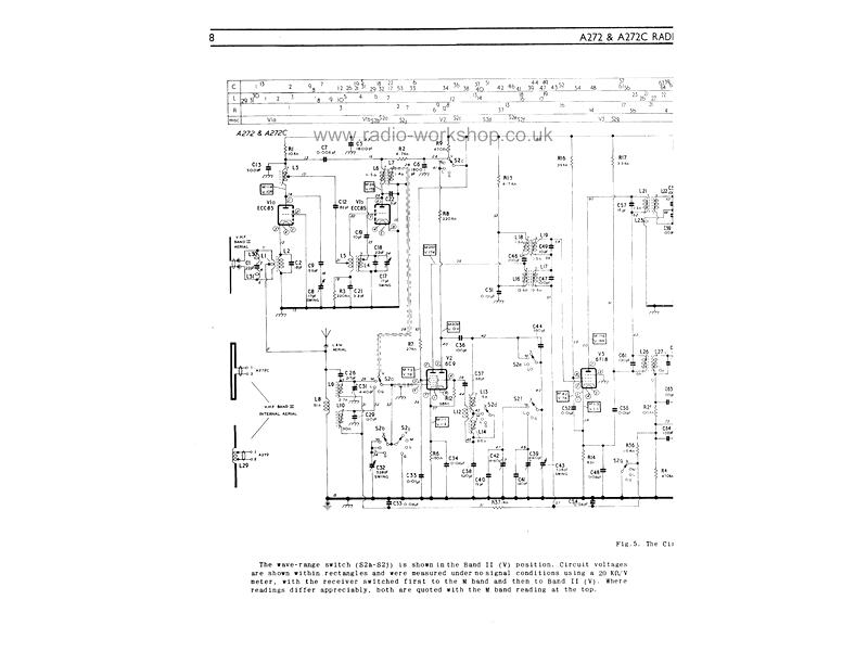
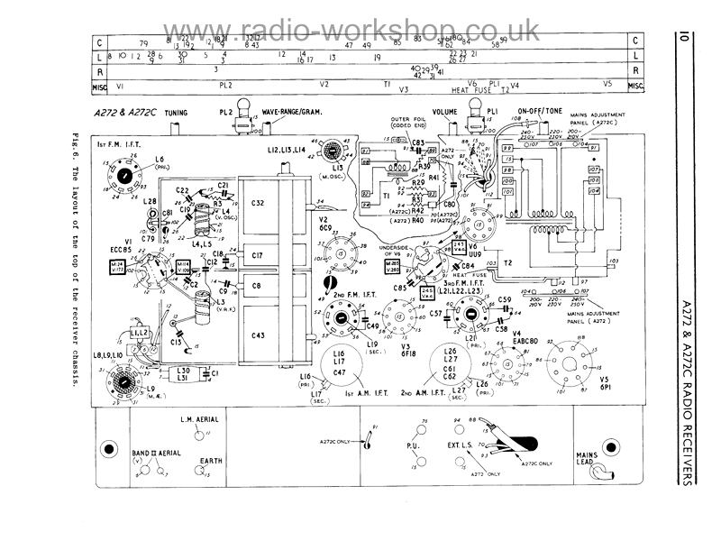
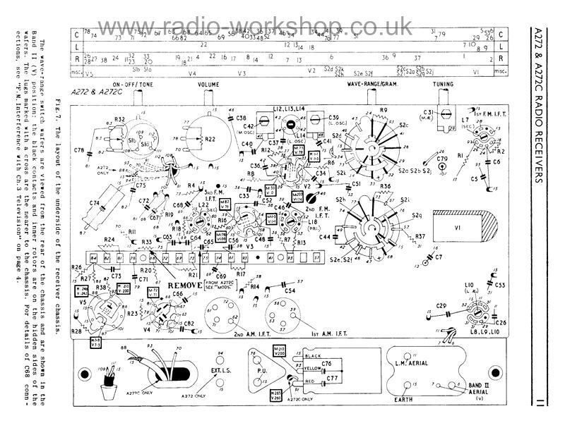
These pictures are faded on purpose, just for this preview. Members get the complete service manual, unfaded, to view and download.
The service manual includes:
- The specification and valve line-up
- Notes on installing the aerial
- Electrical notes on the AM and FM circuits
- Notes on the changes made during production
- The full circuit diagram
- Step by step circuit alignment, including the FM discriminator
- The cord drive, and the layout of the internal aerial
- Parts lists for the electrical and mechanical components